
Construction of 3-Phase
Induction Motor (3-Φ IM)
The three-phase induction motor is the workhorse of industry — simple, robust, and self-starting. This complete guide covers its construction, stator, both rotor types, working principle and key specifications.
Overview & Key Facts
The 3-phase induction motor (3-Φ IM) is the most widely used electric motor in the world. It converts three-phase AC electrical energy into mechanical rotational energy through electromagnetic induction — with no electrical connection to the rotor. This makes it exceptionally reliable, low-maintenance, and cost-effective.

Main Parts of a 3-Phase Induction Motor
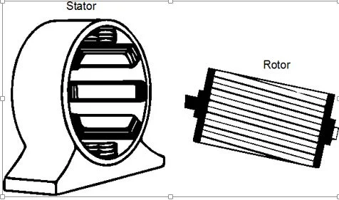
A 3-phase induction motor consists of two fundamental parts — the stationary stator and the rotating rotor — along with supporting components such as bearings, end shields and the outer frame.
Stator Construction
The stator is the stationary part of the motor. It consists of a hollow cylindrical core made of thin silicon steel laminations, stacked together to reduce eddy current losses. The inner surface of the stator core has slots that house the three-phase winding.
- Stator Core: Built from 0.4–0.5mm thick silicon steel laminations, insulated from each other and pressed into a cylindrical frame.
- Stator Winding: Three-phase winding (R, Y, B phases) is distributed in the stator slots, displaced by 120° in space from each other.
- Connection: The stator winding is connected in either star (Y) or delta (Δ) configuration depending on the motor voltage rating.
- Supply: When 3-phase AC supply is applied to the stator winding, it produces a Rotating Magnetic Field (RMF) of constant magnitude.
- Synchronous Speed: The RMF rotates at synchronous speed Ns = 120f/P, where f = frequency and P = number of poles.


When a balanced 3-phase supply is applied to the stator winding, it produces a Rotating Magnetic Field (RMF) of constant magnitude that rotates at synchronous speed. This RMF is the fundamental cause of rotor rotation — it is what makes the induction motor self-starting.
f = frequency (Hz), P = poles
f = 60 Hz (US)
Rotor Construction
The rotor is the rotating part of the motor, mounted on the shaft inside the stator. Like the stator, the rotor core is made of laminated silicon steel to reduce eddy current losses. The rotor carries a short-circuited winding that receives power from the stator purely by electromagnetic induction — there is no direct electrical connection between stator and rotor.
- Rotor Core: Cylindrical laminated silicon steel core mounted on the shaft.
- Rotor Winding: Short-circuited winding — either squirrel cage bars or wound coils.
- Power Transfer: Energy is transferred from stator to rotor by electromagnetic induction (like a transformer).
- Two Types: Squirrel cage rotor and wound rotor (slip ring type).
Both stator and rotor cores use thin silicon steel laminations (0.4–0.5mm) insulated from each other. This breaks up the eddy current paths and dramatically reduces eddy current losses, improving efficiency and reducing heat generation. Without laminations, eddy currents would make the motor extremely hot and inefficient.
Squirrel Cage Rotor
The squirrel cage rotor is the most common type — used in over 90% of all induction motors. It gets its name from its resemblance to a rotating exercise wheel used by squirrels. The rotor consists of copper or aluminium bars embedded in rotor slots and short-circuited at both ends by end rings of the same material.
- Construction: Aluminium or copper conductor bars placed in rotor slots, short-circuited at both ends by end rings.
- No External Connections: The rotor circuit is permanently short-circuited — no slip rings, brushes or external resistance.
- Skewing: Rotor bars are often slightly skewed (twisted) to reduce noise, cogging torque and improve starting.
- Robust & Maintenance-Free: Extremely rugged construction — virtually no maintenance required.
- Fixed Rotor Resistance: Cannot add external resistance — starting torque and current characteristics are fixed by design.


Simple construction, no slip rings or brushes, very low maintenance, high efficiency at full load, lower cost, and suitable for most industrial applications where variable speed is not required.
Wound Rotor (Slip Ring Type)
The wound rotor (also called slip ring rotor) carries a 3-phase distributed winding — similar to the stator winding — connected in star (Y). The three ends of the rotor winding are connected to three slip rings mounted on the shaft. Carbon brushes ride on these slip rings, allowing external resistance to be connected in series with the rotor circuit.
- 3-Phase Winding: Distributed winding in rotor slots, connected in star (Y).
- Slip Rings: Three slip rings on the shaft bring rotor terminals out to external circuits.
- External Resistance: Variable resistance can be inserted in the rotor circuit via brushes and slip rings — controls starting torque and speed.
- Higher Starting Torque: By inserting full external resistance at start, maximum torque can be achieved at zero speed.
- Speed Control: Rotor resistance control allows variable speed operation — useful for fans, pumps, cranes.
- Higher Cost & Maintenance: Brushes and slip rings require periodic maintenance and replacement.
Wound rotor motors are preferred when high starting torque is needed with limited starting current — such as compressors, hoists, cranes and grinding mills — or when speed control is required. For simple constant-speed applications, squirrel cage is always the first choice.
Working Principle & Rotating Magnetic Field
The 3-phase induction motor operates entirely on the principle of electromagnetic induction — hence the name. Understanding this mechanism is essential to understanding why and how the motor starts and runs.
The motor is called an induction motor because power is transferred from stator to rotor purely by electromagnetic induction — exactly like a transformer. There is no direct electrical connection, no commutator, no brushes (in squirrel cage type). This is what makes it so rugged and reliable.
Slip and Speed Relationships
Slip (s) is the most important variable in induction motor analysis. It defines the difference between synchronous speed and rotor speed, and directly controls the magnitude of induced rotor EMF, current and torque.
f = supply frequency, P = poles
Nr = actual rotor speed (RPM)
Typical: s = 0.02 to 0.08 (2–8%)
Full load: 2–5% (squirrel cage)
| Condition | Slip Value | Rotor Speed | Meaning |
|---|---|---|---|
| At start (standstill) | s = 1.0 (100%) | Nr = 0 | Motor just switched on, rotor stationary |
| Full load (rated) | s = 0.02–0.05 | Nr ≈ 0.95–0.98 Ns | Normal operating condition |
| No load (ideal) | s ≈ 0 | Nr ≈ Ns | Near synchronous speed, very small slip |
| Synchronous speed | s = 0 | Nr = Ns | Impossible — no torque produced |
Squirrel Cage vs Wound Rotor — Comparison
- Simple, robust construction
- No slip rings or brushes
- Virtually maintenance-free
- Lower cost
- Higher efficiency at full load
- Lower starting torque
- Fixed rotor resistance
- No speed control via rotor circuit
- Used for: fans, pumps, compressors, conveyors
- 3-phase distributed winding on rotor
- Slip rings and brushes on shaft
- Requires regular brush maintenance
- Higher cost
- Higher starting torque possible
- Variable rotor resistance via slip rings
- Speed control possible
- Reduced starting current
- Used for: hoists, cranes, grinding mills
Conclusion
The 3-phase induction motor achieves its remarkable simplicity and reliability by eliminating all direct electrical contact with the rotor — power is transferred entirely by electromagnetic induction. The stator produces the rotating magnetic field; the rotor responds to it; the difference in speed (slip) is what sustains the torque that drives the load.
The choice between squirrel cage and wound rotor depends on the application: squirrel cage for simple, high-efficiency constant-speed drives; wound rotor where high starting torque or speed control is required. In either case, understanding the construction gives you the foundation to understand motor characteristics, selection, protection and control.
Stator → receives 3-phase supply → produces RMF at synchronous speed Ns. Rotor → cut by RMF → induced EMF → current → torque → rotates at Nr < Ns. Slip = (Ns − Nr)/Ns — always > 0 for torque to exist. Squirrel cage = simple/robust. Wound = high torque/controllable.
⚡ Try Our Free Motor Calculator
Calculate full load current, starting current, HP/kW conversion and cable sizing for 3-phase induction motors — free online.
📈 Open Motor Calculator

good job.
ReplyDelete